- Please select your languages, order to get all infomation that you need
- English العربية Le français Deutsch lingua italiana 日本語 한국어 Português (Portugal, Brasil) русский Español


1.Equal forces on both ends of the piston
2.Force connection direct, torque safe
3.Piston with or without magnets50% space-savings
4.Long strokes up to 8000mm
5.End caps with 3 air connections and adjustable cushioning
6.Fast acceleration and high piston velocity
7.Very flexible in the user's design
8.Non lubricated or lubricated air supply**
The entire tube is slotted throughout its full length. The force istransmitted through the load friction, which is attached to thepiston axle. The design of the piston axle is that way that the innerpart of the piston axle is connected through the slot with theouter part of it, Therefore the force transmission runs as follows:
Air pressure > Piston area > piston axle (inner part)> piston axle(outer part) > load friction > load.
The sealing of the cylinder slot is garanteed by a most preciselygrinded inner steel band. The inner band is kept in position due tomagnet stripes which are placed on both sides of the slot. Inaddition there is an outer steel band covering the slot in order tokeep dust out of inner space of the cylinder.
During piston movement as well as during stillstand of it bothsteelbands are lifted right after the piston seal and led throughthe piston axle by means of a separate own guiding chanel. Beforeand behind the piston axle both bands are covering the slotpermanently again.
| Design | Rodless cylinder, double acting | |||||
| Strokes | ø16 mm | 100-4400mm, in increments of 1mm | ||||
| ø25-50 mm | 100-5700mm, in increments of lmm (longer strokes on request) | |||||
| Air Connection | Ø16 | Ø25 | Ø32 | Ø40 | Ø50 | |
| M5 | G1/8 | G1/4 | G1/4 | G1/4 | ||
| Mounting | Free | |||||
| Forces + moments | see Forces and moments | |||||
| Support Forces | see Deflection Diagram | |||||
| Cushion Length | see Cushion Diagram | |||||
| Temperatures | -10°C~+80°C (Other temperatures on request) | |||||
| Pressure range | 0.5-8.0 bar | |||||
| Medium | compressed air, filtered max. 50μm | |||||
| Materials | Barrel | High-strength anodized aluminum | ||||
| End caps | High-strength anodized aluminum | |||||
| Piston axle | High-strength anodized aluminum | |||||
| Seals | Oilproof synthetic material (NBR: v< 1m/s , VITON: v≥ 1m/s) | |||||
| Sealing bands | Stainless steel | |||||
| Piston caps | Wear proof synthetic material | |||||
| Sliding parts | Wear proof synthetic material | |||||


| Cylinder | Effect Force(N) | Cushioning | Max. allowedload (N) | Max. allowed bendingmoments (Nm) | Max. allowed torque(Nm) | ||
| at 6 Bar | (mm) | OSP | OSP | OSP | |||
| Ø | Y | F | S | L | Ma axial | Mr radial | Mv zentral |
| 16 | 9 | 110 | 15 | 120 | 4 | 0,3 | 0.5 |
| 25 | 14 | 250 | 21 | 300 | 15 | 1 | 3.0 |
| 32 | 18 | 420 | 26 | 450 | 30 | 2 | 4.5 |
| 40 | 22 | 640 | 32 | 750 | 60 | 4 | 8.0 |
| 50 | 28 | 1000 | 32 | 1200 | 115 | 7 | 15.0 |
The figures above are max. values based on light shock free dutyand speed ofv≤ 0,2m/sec [PL-series]-v≤ 0,45m/sec [PLF-series].Max. pressure 6 bar.
An exceeding of the values in dynamic operations, even for shortmoments, has to be avoided.
Attention: Resulting forces could lead to extreme exceedings ofthe values. In case of undefinable situations the above max. valueshave to be reduced by 10-20%.

Pay attention to the following points:
1.If the limits above are exceeded additional shock absorbers are necessary.
2.For piston speeds of more than ≥ lm/s viton seals are recommended.
3.For piston speeds ≤ 0,lm/s (NBR), ≤ 0,2m/s (VITON) slow speed lubrication is necessary see at sperpart kids
4.Maximum duration life will be achieved when piston speeds do not exceed 1m/s.

Diagram Information:
1.Calculated deflections without support of 0,5- 1mm allow exceeding of supporting distance.
2.Calculated deflections without support of 1mm- max 1,5mm require reduction ofthe supporting distance.
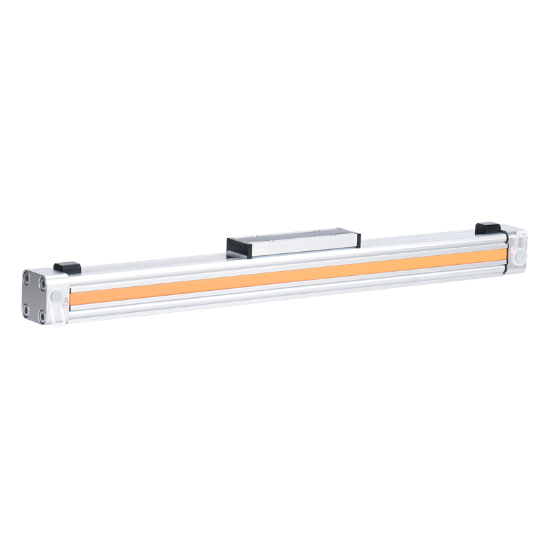
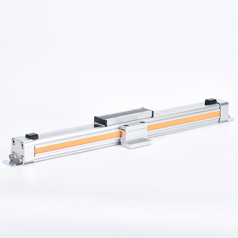
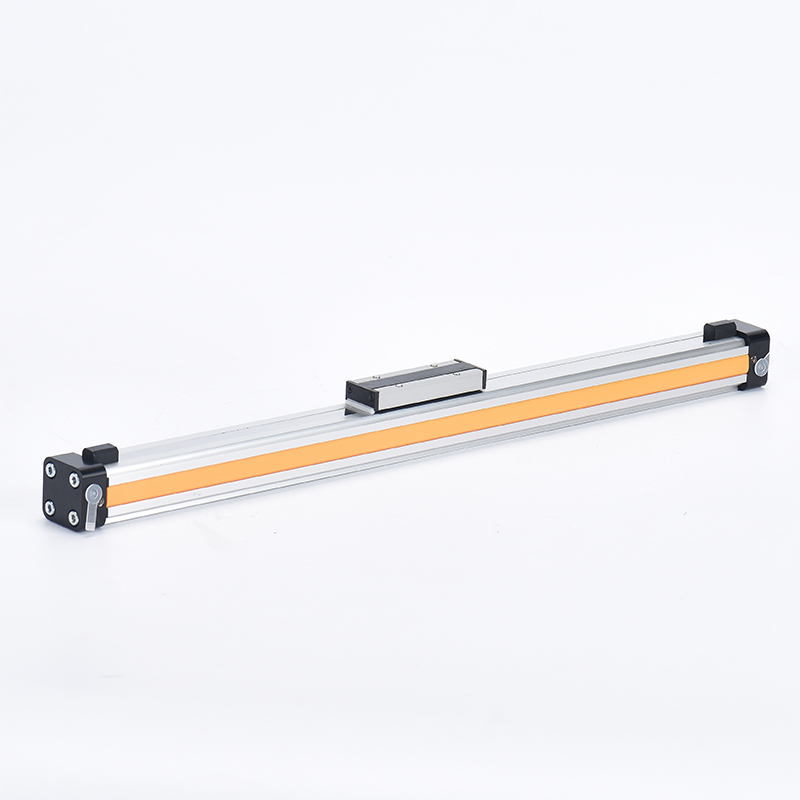
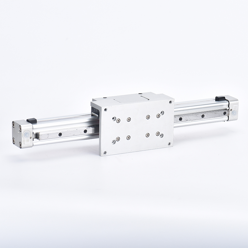
Dimensions of Basic Cylinder OSP-P16-P80

End Cap/Air Connection can be rotated 4 x 90° Series OSP-P16 to P32

Carrier Series OSP-P16 to P80

Dimension Table (mm)
| Cylinder series | A | B | C | D | E | G | H | I | J | K | M | O | S | V | X | Y | Zmin | BW | BX | BY | CF | EN | FB | FH | ZZ |
| OSP-P16 | 65 | 14 | 30 | M5 | 18 | M3 | 9 | 5.5 | 69 | 15 | 23 | 33.2 | 22 | 16.5 | 36 | M4 | 81 | 10.8 | 1.8 | 28.4 | 38 | 3 | 30 | 27.2 | 7 |
| OSP-P25 | 100 | 22 | 41 | G1/8 | 27 | M5 | 15 | 9 | 117 | 21.5 | 31 | 47 | 33 | 25 | 65 | M5 | 128 | 17.5 | 2.2 | 40 | 52.5 | 3.6 | 40 | 39.5 | 8 |
| OSP-P32 | 125 | 25.5 | 52 | G1/4 | 36 | M6 | 15 | 11.5 | 152 | 28.5 | 38 | 59 | 36 | 27 | 90 | M6 | 170 | 20.5 | 2.5 | 44 | 66.5 | 5.5 | 52 | 51.9 | 10 |
| OSP-P40 | 150 | 28 | 169 | G1/4 | 54 | M6 | 15 | 12 | 152 | 34 | 44 | 72 | 36 | 27 | 90 | M6 | 212 | 21 | 3 | 54 | 78.5 | 7.5 | 62 | 63 | 10 |
| OSP-P50 | 175 | 33 | 87 | G1/4 | 70 | M6 | 15 | 14.5 | 200 | 43 | 49 | 86 | 36 | 27 | 110 | M6 | 251 | 27 | - | 59 | 92.5 | 11 | 76 | 77 | 10 |